
Problem-driven overview
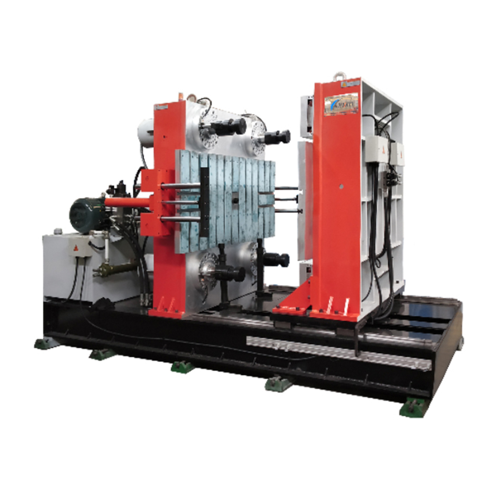
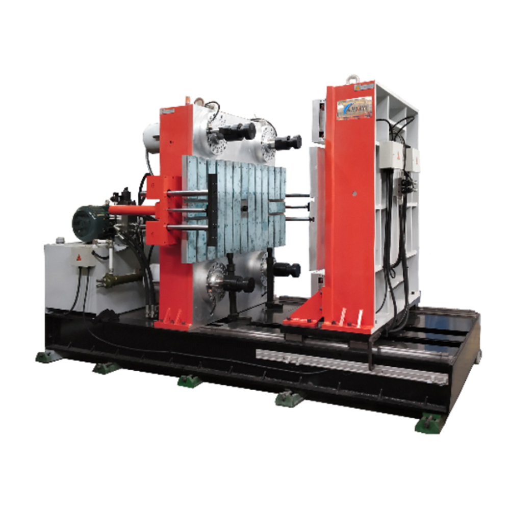
Dimensional drift and flash overflows in liquid silicone rubber (LSR) production cripple yield and force costly rework. In high-volume centers such as Shenzhen’s manufacturing clusters, tolerance windows commonly tighten to ±0.02 mm for connector seals and medical components, making any uncontrolled flash unacceptable. The problem is mechanical, thermal, and rheological: poor seal contact, unstable runner temperature, and variable shot packing combine to produce part swell and flash. Addressing this requires both process architecture and the right platform — beginning with a reliable horizontal rubber injection molding machine designed for LSR dynamics.
Diagnosing root causes
Three failure modes recur. First, incomplete mold sealing at low clamping force lets melt escape at the parting line, producing flash. Second, thermal gradients across the cavity cause differential cure and localized shrinkage, creating dimensional instability. Third, inconsistent shot size and injection speed change shear heating and viscosity, shifting part dimensions between cycles. Trackable metrics — cavity pressure profile, mold surface temperature, and shot-to-shot mass — reveal which mode dominates on a given tool.
Protocol components and machine-level features
The Precision Seal Protocol layers hardware and control strategies. Mechanically, a robust platen alignment system and high-resolution position feedback prevent parting-line gaps during peak packing. Hydraulics or servo drives must deliver repeatable clamping force with minimal compliance. Thermal control calls for segmented mold heating and active cooling channels to collapse gradients. On the control side, closed-loop injection with pressure and displacement profiles stabilizes shot size and packing. These measures pair best with a modern horizontal moulding machine that exposes runner temperature controls and provides high-frequency cavity sensors. Industry terms: runner balancing, clamping force, shot size.
Operational best practices
Start with baseline mapping: run pressure and temperature sweeps across the expected process window to create a process stability matrix. Lock the injection speed that yields minimal shear heating and establish a short, firm packing phase rather than prolonged packing that can cause flash. For medical components, integrate ISO 13485-compliant traceability on every cycle so material lot and process history accompany the part. Tool maintenance matters — regular verification of mold face wear and venting integrity prevents gradual creep in flash generation. Small adjustments pay off; reduce packing pressure in 5–10% steps and monitor dimensional response rather than changing multiple variables at once.

Common mistakes and practical alternatives
Teams frequently chase tighter tolerances by simply increasing clamp tonnage — a band-aid that intensifies mold wear and raises energy cost. Another error is ignoring runner temperature stability; an unheated or uneven runner will change shot viscosity and defeat precision. Alternatives include switching to valve-gated runners or adjusting runner insulation to keep melt uniform across cavities. For low-volume prototyping, insert soft stops or use removable shim packages to trial tolerance changes without full mold rework.
Three golden rules for selecting tools and strategies
1) Prioritize controllability: select machines with closed-loop injection and high-resolution position encoders so shot size and clamp position are repeatable within micro-scale bands. 2) Insist on thermal zoning: choose molds and machines that allow segmented heating and active cooling to flatten gradients across the cavity. 3) Instrument early: install cavity pressure and mold-surface temperature sensors during tool qualification to build the control maps that prevent flash and dimensional drift. These rules translate directly into measurable returns: higher first-pass yield, fewer scrap cycles, and predictable dimension distributions.
Closing assessment
Implementing the Precision Seal Protocol reduces flash incidence and tightens dimensional stability by combining machine selection, thermal management, and closed-loop process control — tangible outcomes that production engineers can quantify via yield and Cp/Cpk metrics. The path is practical and machine-dependent; when properly executed, teams in production hubs from Shenzhen to Stuttgart realize consistent parts without excessive clamp force. HWAYI sits at the intersection of those machine capabilities and application knowledge — a partner that supplies platforms tuned for LSR precision. – Precision delivered.